
Unlock the hidden features of "Charging while powered off" and "Wake up with keyboard/mouse" on your mini PC.
author: VENOEN
2025-12-29
Unlock the hidden functions of "Power Off and charge" and "Keyboard/Mouse Wake-up" on the mini computer
Applicable models: GT-12/13 generation H series models
Introduction
Have you ever encountered such a problem: in order to make your mini PC more power-efficient, when it goes to sleep or is shut down, you find that:
Introduction
Have you ever encountered such a problem: in order to make your mini PC more power-efficient, when it goes to sleep or is shut down, you find that:
It cannot be awakened by mouse or keyboard. You must press the power button on the body.
If you want to charge devices such as headphones and mobile phones through the USB port of a mini PC, you must keep the computer on throughout the process.
This is actually not a design flaw but the default energy-saving setting. But the good news is that there is a practical "Easter egg" function hidden on the motherboard of this mini PC. With just a simple modification to the jumper cap, you can perfectly solve the above pain points. Today, let's unlock this feature step by step.
If you want to charge devices such as headphones and mobile phones through the USB port of a mini PC, you must keep the computer on throughout the process.
This is actually not a design flaw but the default energy-saving setting. But the good news is that there is a practical "Easter egg" function hidden on the motherboard of this mini PC. With just a simple modification to the jumper cap, you can perfectly solve the above pain points. Today, let's unlock this feature step by step.
I. Prepare the tools
"PH2 screwdriver"
"PH0 screwdriver"
Tweezers
Ii. Operating Guide
"PH0 screwdriver"
Tweezers
Ii. Operating Guide
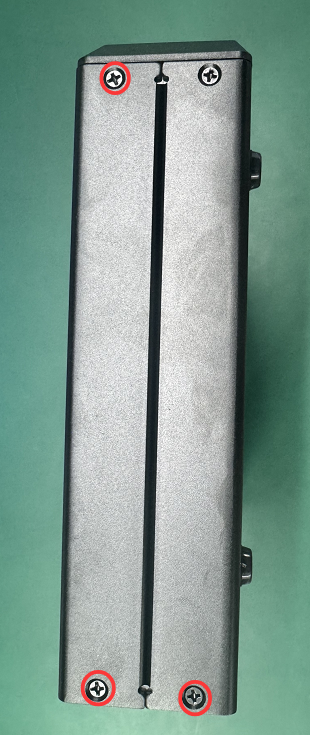
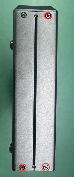
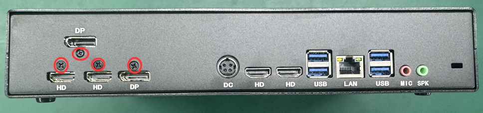
2.1 When disassembling the GT model in a power-off state, 10 screws (9 M3 and 1 M2) need to be removed to open the case.
There are three on the left side of the case
Three on the right side
Four on the rear side
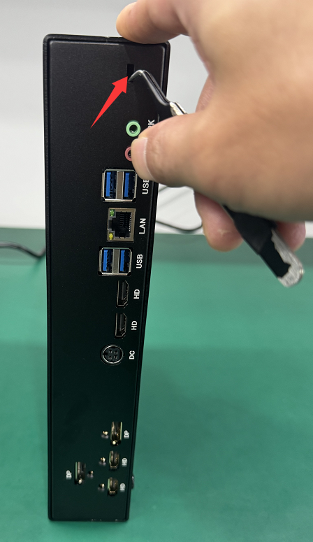
2.2 Use tweezers, insert them into the anti-theft lock hole, and pull out the rear side baffle.
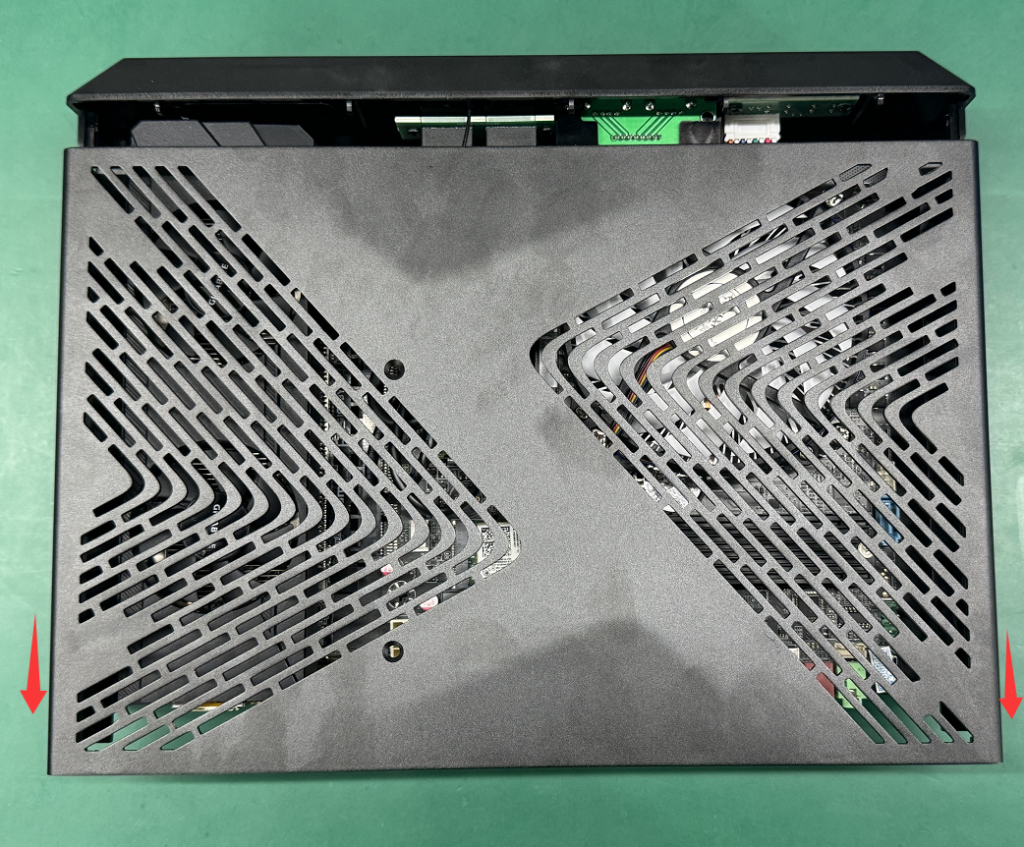
2.3 Pull out the upper shell towards the rear baffle.
Three, find the "USB_POWER" pin header on the motherboard
This set of pins has three pins. We number them as [1] [2] [3]
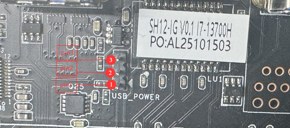
Default position (1-2 short-circuited) : The jumper cap is connected to pins [1] and [2]. At this point, when the USB3.0 port is turned off or in sleep mode, the power will be cut off.
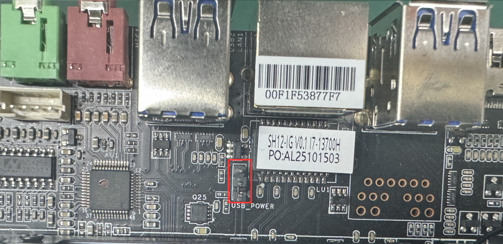
The operation process for continuous power supply to the USB3.0 port in the off/sleep state:
Use tweezers to gently pull out the jumper cap at the default position vertically upwards.
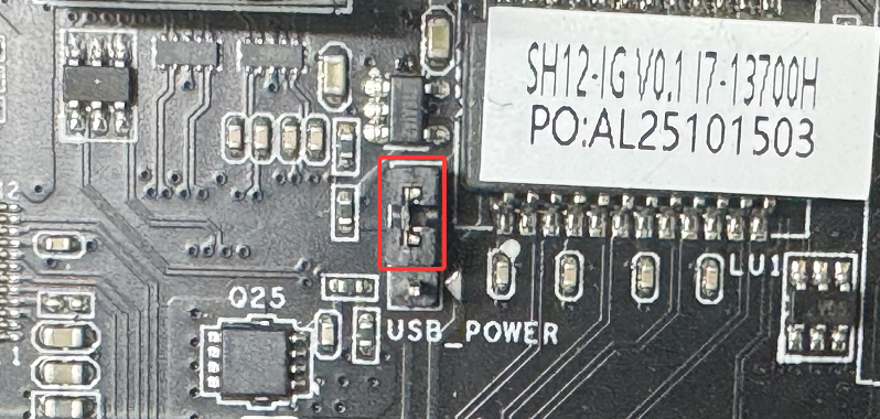
Then accurately place it on the other two target pins ([2] and [3]).
After confirming that the jumper cap is in good contact with the pins, it can be installed in the chassis (you can do not tighten the screws first and fix it after the test is successful).
Then accurately place it on the other two target pins ([2] and [3]).
After confirming that the jumper cap is in good contact with the pins, it can be installed in the chassis (you can do not tighten the screws first and fix it after the test is successful).
Iv. Testing Functions
Connect all the cables (Note: The keyboard and mouse need to be connected to the USB3.0 port), and then power on.
Put the mini PC to sleep. At this point, if you try moving the mouse or pressing a key on the keyboard, the computer should be awakened immediately.
When the device is turned off, insert a mobile phone or other USB device into the USB3.0 port. The device should show that it is charging.
Notes
Put the mini PC to sleep. At this point, if you try moving the mouse or pressing a key on the keyboard, the computer should be awakened immediately.
When the device is turned off, insert a mobile phone or other USB device into the USB3.0 port. The device should show that it is charging.
Notes
Make sure to cut off the power throughout the operation to avoid short circuits that could damage the motherboard.
This jumper only controls the power supply of the four blue USB ports at the rear of the motherboard. The front USB2.0 port cannot be configured with continuous power supply function.
This jumper only controls the power supply of the four blue USB ports at the rear of the motherboard. The front USB2.0 port cannot be configured with continuous power supply function.
Payment Account Change Notice
Steps to enable Secure Boot in BIOS
