
Common configuration guidelines in BIOS for H4T-10th generation models
author: VENOEN
2025-08-27
Common BIOS configuration guidelines for H4T-10 models
Function 1: RS232/RS422/RS485 switching method and pin definition
1.1, the model COM1 and COM2 only support RS232 working mode, COM3, 4, 5, 6 support switching RS485 or RS422 working mode;
1.2. Switching method: Press the switch button and quickly press the keyboard (a wired keyboard is recommended) Del key to enter the BIOS Setup screen, and choose Advanced>ITE Super IO Configuration>Serial Port (3-4-5-6)Configuration>Com Mode Select the required working mode. The default working mode is RS232, RS422/RS485 is optional. After the configuration is complete, press F4 to save and exit.
1.2. Switching method: Press the switch button and quickly press the keyboard (a wired keyboard is recommended) Del key to enter the BIOS Setup screen, and choose Advanced>ITE Super IO Configuration>Serial Port (3-4-5-6)Configuration>Com Mode Select the required working mode. The default working mode is RS232, RS422/RS485 is optional. After the configuration is complete, press F4 to save and exit.
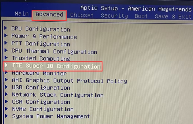
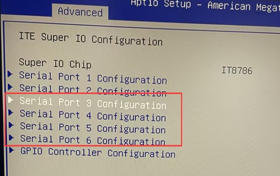
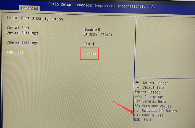
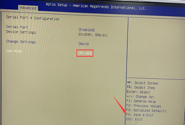
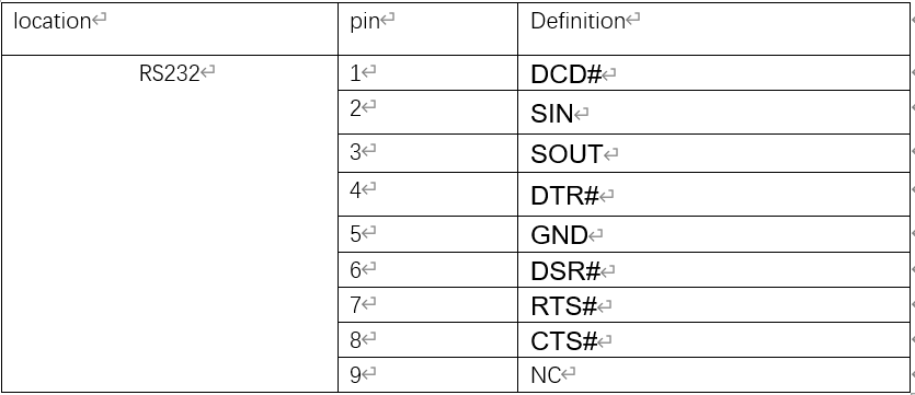
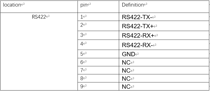
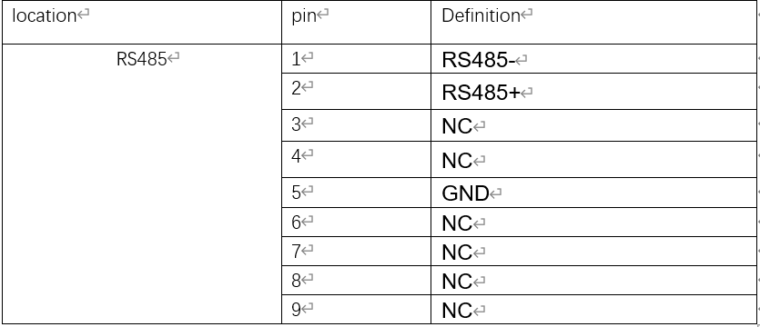
- 1.3, the pin definition of DB 9pin will change after switching the working mode, please refer to the following RS232, RS422, RS485 pin definition, so that you can correctly connect COM peripheral products, to achieve communication between computer and COM peripheral products;
RS232 pin definition
- RS422 pin definition
- Rs485 pin definition
Function 2: GPIO input and output configuration, pin definition
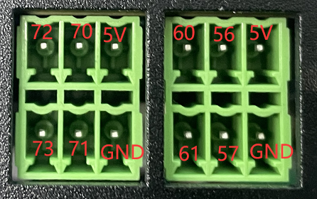
- 2.1. GPIO number and default definition
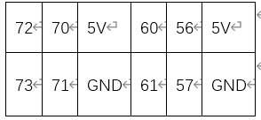
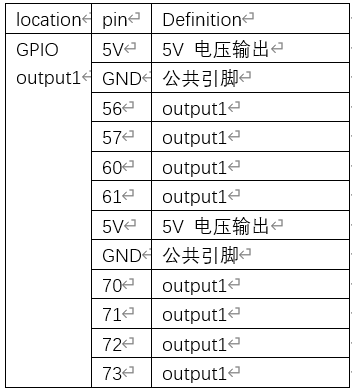
- 2.2 Overview of GPIO
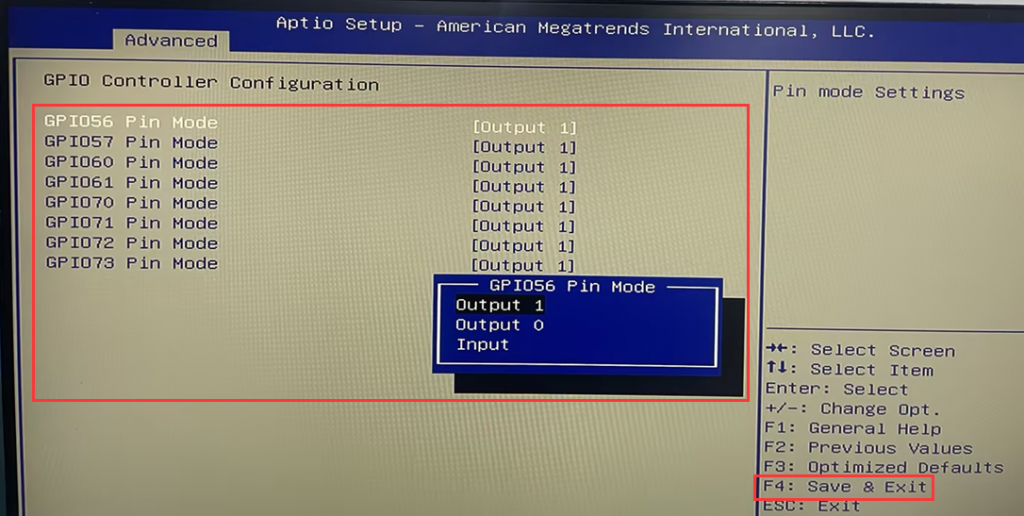
- Supports eight GPIOs. The default BIOS working mode is output 1. Three BIOS modes are available.
- output 1: When this mode is selected, the 5V pin is the common pin, 1 represents the high level, and there is a 5V voltage output when connected with the 5V pin.
- output 0: When selecting this mode, the 5V pin is used as the common pin, and 0 represents the generation low level. When connecting with the 5V pin, there is no 5V voltage output, and it is suitable for the connection of peripheral products that do not need 5V power supply.
- Input: When this mode is selected, the GND pin is the common pin and the input voltage is 5V. This mode does not support switching between high and low levels. If the power supply voltage of your peripheral product is greater than 5V, you should use NPN wiring to supply power to the peripheral product.
- Disclaimer:
- The GPIO port does not support any third party voltage output or output, otherwise the motherboard or port will be damaged. If the GPIO port or computer is damaged due to improper operation of the user, it is not covered by the warranty!
- GPIO functions as a general input and output port. You need to write a GPIO control program according to your requirements. For hardware manufacturers, we only provide GPIO pin definition and basic information. Programming problems, can not provide any technical support!
- 2.3. Working mode switching method:
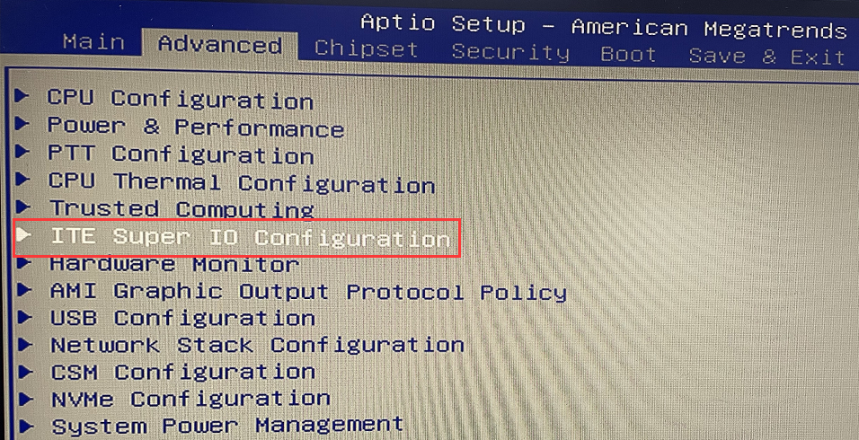
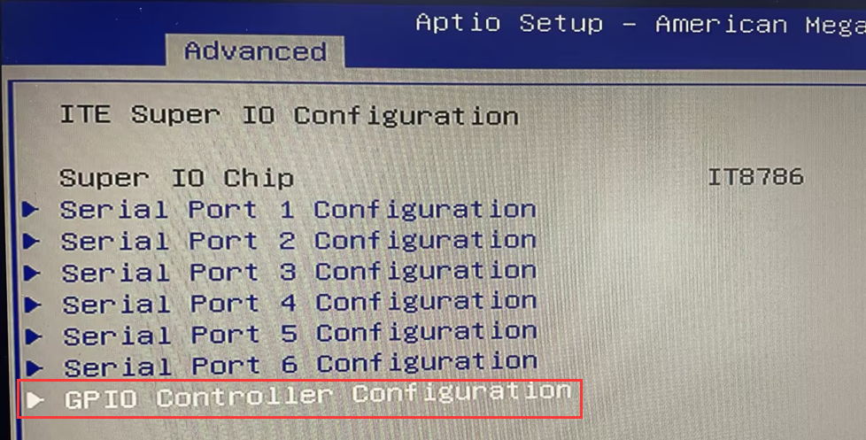
- ※Press the switch button and quickly press the keyboard (Wired keyboard is recommended) Del key to enter BIOS Setup and select Advanced>ITE Super IO Configuration>GPIO Configuration> GPIO56-GPIO 73 pin Select the desired working Mode in mode, press F4 to save the configuration and exit.
Function 3: Power-on self-starting
- 3.1, the model is positioned as an industrial computer, the factory default to open the power self-start function, if you do not need the function, please follow the following steps to close.
- Closing method:
- Open the bottom shell when the power is off;
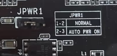
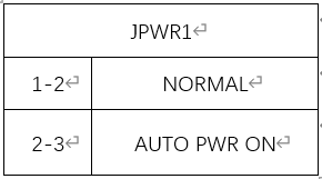
- Find the JPWR1 row of pins on the motherboard, move the jump cap on the row of pins to the pin1 and pin2 pins, you can turn off the power self-start function.
Function four: timed boot
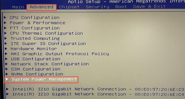
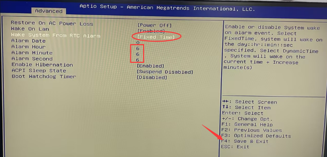
- 4.1. Press the switch button and quickly press the Del key on the keyboard (Wired keyboard is recommended) to enter the BIOS Setup, and then select Advanced>System Power Management>Wake System From RTC Alarm to set the Settings to Fixed Time.
- When the Alarm Date is set to 0, it indicates daily.
- Set Alarm Hour,Alarm Minute, and Alarm Second parameters as required. Press F4 to save the Settings and exit.
Function 5: Enable PXE
- 5.1 What does PXE mean?
- PXE is short for "Preboot eXecution Environment". It is a network boot protocol that allows a computer to boot over a network rather than from a local hard disk or other storage device. With PXE, a computer can connect over a network to a special server called a PXE server to get an operating system or other boot loader. This is useful for remote management and large-scale deployment of computers, such as in enterprise environments.
- In your computer's BIOS or UEFI firmware, you can configure the boot order so that when a network connection is detected, you attempt to boot via PXE. This allows you to use PXE if there is a problem with the computer's local storage device or if you need to install the operating system through network boot.
- 5.2. Enable PXE
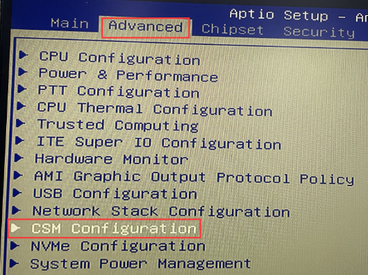
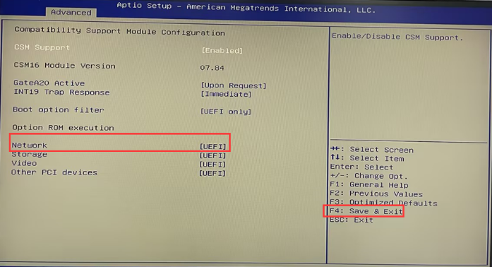
- Press the switch button, quickly press the Del key on the keyboard (Wired keyboard is recommended) to enter the BIOS Setup, choose Advanced>CSM Configuration>Network to configure UEFI, and press F4 to save the configuration and exit.
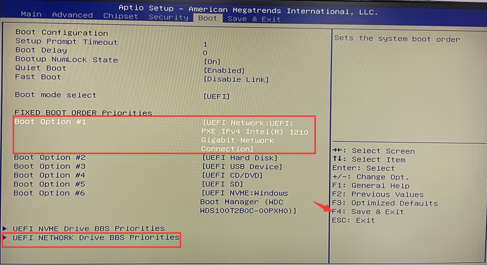
- After the restart, quickly press the Del key on the keyboard to enter the BIOS again, choose Boot>UEFI NETWORK Drive BBS Prioities to select network adapters, and configure network adapters to start devices first in Boot Option #1. The NIC name is UEFI Network :UEFI PXE IPV4 intel(R) I210...... Then press F4 to save the configuration and exit.
Function 6: Network Wake up (wake-on-LAN)
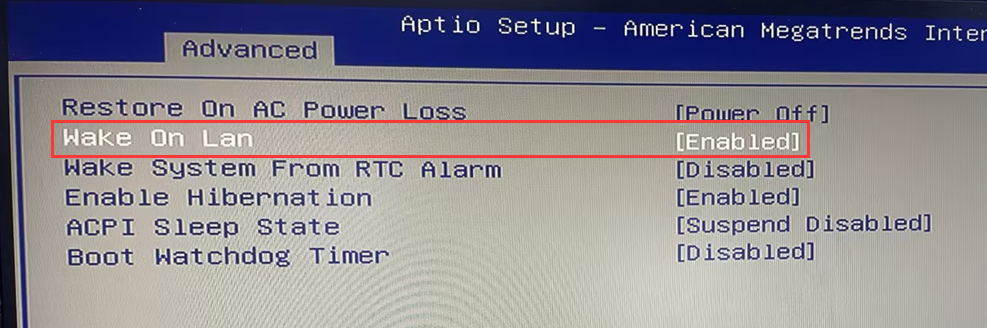
- 6.1. Wake on Lan is enabled by default in the BIOS. You do not need to enter the BIOS to set any parameters.
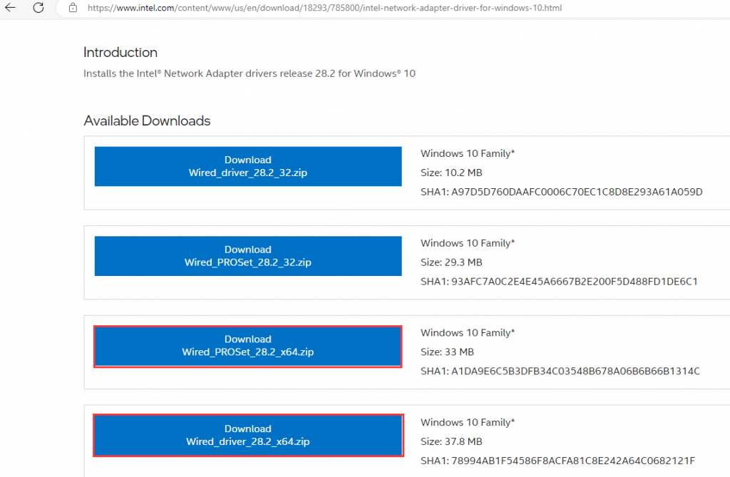
- 6.2. In Windows10\11 system environment, download and install Wired_driver_28.2_X64 (priority installation of drivers) and Wired_PROSet_28.2 to enable NIC wake-up permissions. Download address://www.intel.com/content/www/us/en/download/18293/intel-network-adapter-driver-for-windows-10.html,According to the system type, download the corresponding driver and tool versions. Here, we choose to download the X64 version.
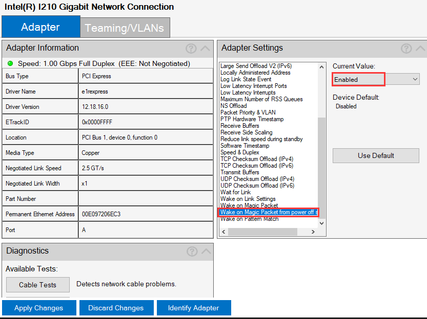
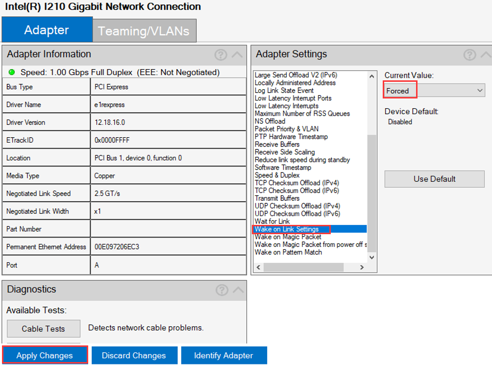
- 6.3. Wired_driver_28.2_X64 and Wired_PROSet_28.2 After the installation is successful, run the intel PROSet Adapter as the administrator and select the intel I210 Gigabit Network Connection. Set Wait for Link to On, Wake on Magic Packet from power off state to Enabled, Wake on Link Settings to Forced, and click Apply Changes, and then the intel I210 Gigabit Network Connection #2 network card is configured as usual.

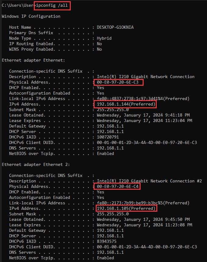
- 6.4 Connect the computer that needs to be awakened and the computer that sends the wake-up command to the same LAN (wake up in a non-LAN environment, you need to have a public IP address or use a third-party tool to penetrate the Intranet to wake up, which is not introduced here), enter the operating system, Win+R key to start running, enter CMD to hit the command prompt during running. Enter ipconfig /all to query and record the MAC address and IP address of the NIC.
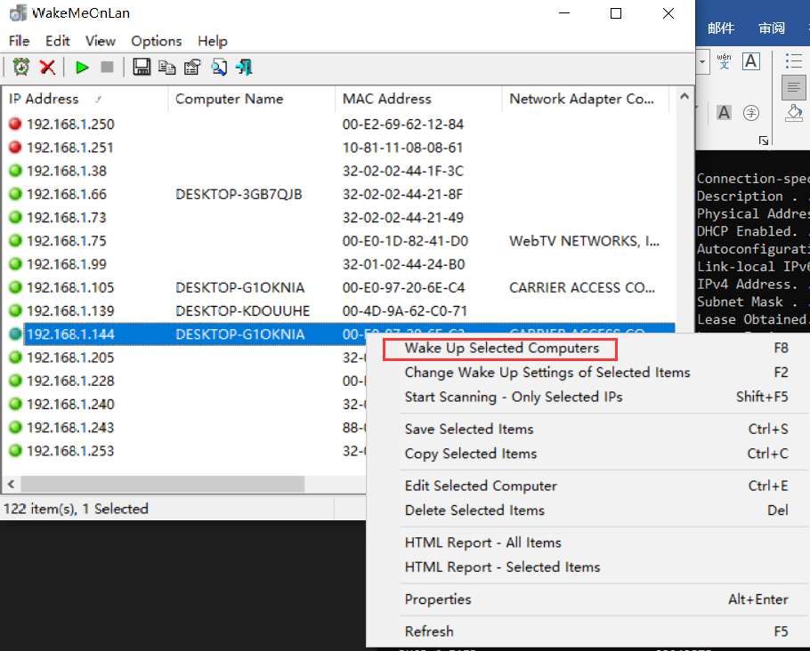
- 6.5. Download and install the wake up tool. Take WakeMeOnLan as an example. Scan out all online IP addresses on the LAN, find the MAC address and IP address that have just been recorded from the list, and then shut down the computer that needs to be awakened. Wake UP Selected Computers to wake up normally.
What should I do when the Blue Screen of Death occurs in Windows 11? Error code WHEA_UNCORRECTABLE_ERROR
How to configure UEFI boot in a BIOS that supports UEFI and Legacy boot modes?
